Feb 27, 2011

Oscillators

There are literally dozens of types of oscillators in existence so it would be impossible to sufficiently discuss them all in single blog entry. I lack the time, enthusiasm, and knowledge of all the different variations to cover them in the depth they deserve. Originally, I had intended to cover harmonic, LC, and quartz crystal oscillators in this post. However, after starting to write about Wein-bridge (harmonic) oscillators I felt that even covering those three would be too much for one post. Therefore, I will focus my attention on the classic Wein-bridge oscillator and reserve LC and quartz crystals for the future.

The simulation I ran in my last blog entry used an AC source to emulate the oscillator in the comparator circuit. In reality, oscillators are very similar to AC sources but not quite the same thing. An oscillator is a device that produces an AC waveform, which does not necessarily always mean a sine wave. What’s cool about oscillators is that they are actually “controlled chaos” devices. In any circuit system, stability is a high priority. You want your design to be able to adapt to constant variations in circuit parameters such that the application itself maintains its intended performance. Oscillators, however, are the result of amplifiers that have been intentionally driven towards instability to produce a predictable result.

In order for oscillators to maintain oscillations, they need to meet two criteria:
  
  1. The gain of the oscillator must be greater than or equal to unity.
  2. The phase shift from the output back to the inputs must be zero degrees.

These two constraints are known as the Barkhausen stability criterion after Heinrich Georg Barkhausen, a German physicist who made large contributions to control theory and electromagnetics. 

Let’s take a look at what I mean with the classic Wein-bridge oscillator. Wein-bridge oscillators are very easy to design and can sustain oscillation frequencies up to 1MHz assuming a high-frequency op-amp is not used in the design. They are popular in the market because they can produce low-noise and achieve very small total harmonic distortion (THD). I have seen designs with a THD of less than 1 percent.

As you can see in Figure 1, the oscillator has two feedback paths from the output of the op-amp back to the positive (+) and negative (-) input terminals. The positive feedback path creates the oscillations while the negative path controls the gain of the system. The oscillator in Figure 1 was designed for an oscillation frequency of 2kHz.

Figure 1. Wein-bridge oscillator schematic

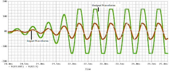
It’s important to notice that there are no input signals at either the non-inverting (+) or inverting (-) pins of the op-amp (however there are rail voltages to supply power). These types of oscillators are, essentially, able to create something out of nothing because they amplify ambient noise signals to start to oscillations. The op-amp itself generates small noise signals from the operation of the internal transistors. Those signals travel through the feedback loop of the oscillator over and over gradually gaining in amplitude after each pass. Figure 2 illustrates how the oscillator produces a very small signal for the first 15ms or so and then starts to build up until the loop can sustain oscillation.


Figure 2. Output waveform of Wein-bridge Oscillator

To verify the oscillation frequency, we can look at the fast Fourier transform (FFT) of the loop. FFTs are a discrete representation of the harmonic content of a system. Figure 3 shows a clear spike at 2.0000kHz, where the oscillation frequency should occur. The FFT confirms that this loop oscillates as it was designed. There are two final important points I want to point out about this design.


Figure 3. FFT of Wein-bridge oscillator

First, Figure 2 shows the oscillations as they occur in the simulation, but you may notice that the peaks of the waveform are flat rather than a smooth curve. This is because the signal is “clipping”. The output waveform of the op-amp can never achieve a higher voltage than is powering the op-amp. When the circuit gain pushes the output waveform beyond the voltage used to power the op-amp, we say it is “clipped”. If you look closely, you will see that voltage of the oscillation levels off at 15V and -15V, the voltages powering the op-amp. It is in the nature of oscillations to increase in magnitude if they are not controlled. This design lacks any form of amplitude stabilization circuitry because I was going for demonstration of concept in this blog entry. With a couple of diodes, you could limit the peak voltage of the oscillation and keep it away from the rail voltages at both extremes of the sine wave.

Second, often times these oscillators are designed so that white noise is introduced into the system when power is supplied to start the oscillations quickly. The waveform in this simulation did not reach steady-state until about 25ms from the time power was applied. For humans, 25ms seems inconsequential but in the realm of computers and integrated circuits 25ms is an eternity. This design would be impractical for many applications but more complex versions can be found in many types of active filter and radio platforms today.

For one last proof, Figure 4 shows how this oscillator design satisfies the Barkhausen criteria. As you can see from the picture, the input (red) voltage waveform is in phase (meaning there is a 0 degree phase shift from input to output) with the output voltage waveform (green). Also, the red waveform’s amplitude is lower than the green meaning that the gain of the system is greater than one. Therefore, this oscillator meets both Barkhausen criteria.

Figure 4. Input (red) and output (green) waveforms of Wein-bridge oscillator

I will do another blog in the future on LC and quartz crystal oscillators. They generate the same result but in different ways than the Wein-bridge. Hopefully, this entry has revealed some of the design considerations required to produce oscillations that are so critical to the ever expanding array of electronics in the world today. Next up, pulse-width modulation!

Feb 13, 2011

Comparator Operation

My first choice for a blog entry, being a power electronics fan, was to discuss pulse-width modulation (PWM) schemes and how they are applied across various applications. The idea behind PWM is relatively simple but the implementation can be complex in control theory. Given the level of complexity involved, I want to do a series of build ups before demonstrating the idea completely.

The concept of PWM can be conceptualized using a comparator with a reference voltage and an oscillator. This entry will discuss comparators.

A comparator is an electronic component that compares either voltage or current inputs and generates an output if the test input is greater than the reference input. There are variations having to do with the power supplied to the comparator and the logic outputs required, but conceptually the idea is pretty consistent across all applications. There are analog comparators like the LMP7300 and digital comparators like the CD4063B from Texas Instruments, which compares binary inputs.   

Some manufacturers make dedicated comparator ICs for performance applications (digital signal processing, high speed gate drivers, logic gates, etc.). These ICs tend to react to changing input signals faster than other op-amp based comparators and are better suited to handling high frequency input signals.

I like to show people a concept rather than explain it qualitatively so let’s look at an example of a comparator. The schematic below is a makeshift comparator using an ideal op-amp and a 2N3906 PNP transistor. I will do a full blog on op-amps and transistors in the future but for now just think of the circuit as a black box that outputs logic high or low. 

Figure 1. A comparator circuit model
 
The circuit has a static reference voltage of 3V placed on the inverting (-) pin of the op-amp and a secondary input voltage on the non-inverting (+) pin for comparison. The figure below demonstrates how the comparator reacts to increasing input voltage. As you can see, once the green (input) voltage exceeds the red (reference voltage) the op-amp switches on the transistor and the voltage across the output goes from 0V to 5v. Some may have noticed that the rise from 0V to 5V is not instantaneous. The output starts to increase from zero around 2.8V on the input and does not reach the full 5V output until an input of about 3.2V. I do not want to get into the details in this blog entry, but I will address this slow rise in future blogs related to op-amps. Suffice it say for now the response time of the op-amp prevents ideal operation of the system as a whole.

The op-amp is operating in an “open loop” state in this design meaning that there is no feedback network from its output pin to its input pins. Op-amps are manufactured with very high open loop gains for reasons I will go into in future blogs. The high gain amplifies the difference in signal level between the op-amp inputs and drives the output to the rails (or equal to the voltage powering the op-amp). In this case, the rail voltage is 5V.

Figure 2. Input to Output Voltage Relationship of a Comparator 

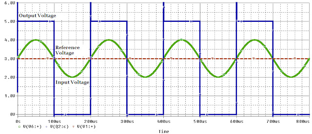
Hopefully by now the basic operation of a comparator has been explored. The last figure shows what happens when a time-varying signal is introduced as an input and compared to the static input voltage.

Figure 3. Comparator Operation with a Time-Varying Input Signal

As you can see, each time the green input voltage drops below the red reference voltage the output of the system is driven low (0V). When green goes higher than red, the output is driven high (5V). The high frequency spikes at the beginning of the square wave output are a product of the switching components in the circuit diagram and are, again, something I will explore in future blogs. With a more robust design, you can get a more complete waveform using RC snubbers on the output.

Today, comparators can be found in thousands of ICs on the market either as stand-alone parts or integrated into more generalized chips. Control and logic schemes associated with these devices are much, much more complex than what I have discussed in this blog, but my goal is to give my readers at least a marginal understanding of the electronics that appear in nearly everything these days.

Feb 2, 2011

Tablets and Tech Convergence

Two years ago, a tablet computer was basically a laptop with optical character recognition (OCR). Since Apple launched the iPad in the Spring of 2010, “tablet” has taken on an entirely new association and created a new market. Some have gone as far to say that the iPad is a “breakthrough” device when it is really a product of technological convergence.
Technological convergence is the idea that niche devices will ultimately be incorporated into an all-in-one media solution. Before the release of tablets like the iPad or the Samsung Galaxy Tab, e-readers like the Amazon Kindle or the Barnes & Noble Nook were the dominant forms of personal media devices outside MP3 players and smart phones. Now, e-readers are taking a substantial hit from tablet growth and failing to meet projected sales numbers. While the e-reader is unlikely to be phased out completely, tablets have hindered their expansion by offering people a merger of an e-reader and a smartphone (minus the phone for now) in a package that amounts to a portable LCD screen. At this year’s CES there were over 100 new tablets on display, most of which were hidden behind walls of glass beyond the reach of salivating consumers. Complaints about the iPad go so far as to say it isn’t convergent enough with a lack of voice-over-internet protocol (VOIP) capability or a camera, but I attribute those deficiencies to Apple’s marketing department. The iPad 2 is slated for release in 2011 and all reports indicate it will be the iPad plus a camera.

The Apple 'iPad,' a new tablet computing device, is shown in this publicity photo from Apple released to Reuters on Wednesday.
The "revolutionary" iPad from Apple

While I do think that tablets have the ability to change the way we use technology, I also think their potential for backsliding is greater than any other portable media device available today. What happens when someone releases a tablet with a slide-out keyboard? Do we call it a giant smart phone or a netbook? Will netbooks even exist in 5 years as Moore’s law continues to improve computing power in smaller packages?
In the perpetual quest for a technological singularity, tablets will likely get closer than any consumer product in recent years. I have seen them dim lights, change channels, and control entire planetariums, but don’t toss out your remote just yet. The days of being able to dock your tablet in a desktop cradle for home use and carry it on the road during your daily commute are far away if they ever come. The rise of cloud computing makes this scenario somewhat practical yet still pretty unlikely.
I have no doubt that as tablets continue to evolve the lines between consumer products will become increasingly b lured. One day, people will look back and wonder why they paid money for superfluous gadgets when their tablet does it all; maybe there’s an app for that…