My first choice for a blog entry, being a power electronics fan, was to discuss pulse-width modulation (PWM) schemes and how they are applied across various applications. The idea behind PWM is relatively simple but the implementation can be complex in control theory. Given the level of complexity involved, I want to do a series of build ups before demonstrating the idea completely.
The concept of PWM can be conceptualized using a comparator with a reference voltage and an oscillator. This entry will discuss comparators.
A comparator is an electronic component that compares either voltage or current inputs and generates an output if the test input is greater than the reference input. There are variations having to do with the power supplied to the comparator and the logic outputs required, but conceptually the idea is pretty consistent across all applications. There are analog comparators like the LMP7300 and digital comparators like the CD4063B from Texas Instruments, which compares binary inputs.
Some manufacturers make dedicated comparator ICs for performance applications (digital signal processing, high speed gate drivers, logic gates, etc.). These ICs tend to react to changing input signals faster than other op-amp based comparators and are better suited to handling high frequency input signals.
I like to show people a concept rather than explain it qualitatively so let’s look at an example of a comparator. The schematic below is a makeshift comparator using an ideal op-amp and a 2N3906 PNP transistor. I will do a full blog on op-amps and transistors in the future but for now just think of the circuit as a black box that outputs logic high or low.

Figure 1. A comparator circuit model
The circuit has a static reference voltage of 3V placed on the inverting (-) pin of the op-amp and a secondary input voltage on the non-inverting (+) pin for comparison. The figure below demonstrates how the comparator reacts to increasing input voltage. As you can see, once the green (input) voltage exceeds the red (reference voltage) the op-amp switches on the transistor and the voltage across the output goes from 0V to 5v. Some may have noticed that the rise from 0V to 5V is not instantaneous. The output starts to increase from zero around 2.8V on the input and does not reach the full 5V output until an input of about 3.2V. I do not want to get into the details in this blog entry, but I will address this slow rise in future blogs related to op-amps. Suffice it say for now the response time of the op-amp prevents ideal operation of the system as a whole.
The op-amp is operating in an “open loop” state in this design meaning that there is no feedback network from its output pin to its input pins. Op-amps are manufactured with very high open loop gains for reasons I will go into in future blogs. The high gain amplifies the difference in signal level between the op-amp inputs and drives the output to the rails (or equal to the voltage powering the op-amp). In this case, the rail voltage is 5V.
 Figure 2. Input to Output Voltage Relationship of a Comparator
 Hopefully by now the basic operation of a comparator has been explored. The last figure shows what happens when a time-varying signal is introduced as an input and compared to the static input voltage.
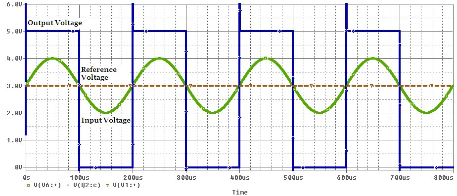
Figure 3. Comparator Operation with a Time-Varying Input Signal
As you can see, each time the green input voltage drops below the red reference voltage the output of the system is driven low (0V). When green goes higher than red, the output is driven high (5V). The high frequency spikes at the beginning of the square wave output are a product of the switching components in the circuit diagram and are, again, something I will explore in future blogs. With a more robust design, you can get a more complete waveform using RC snubbers on the output.
Today, comparators can be found in thousands of ICs on the market either as stand-alone parts or integrated into more generalized chips. Control and logic schemes associated with these devices are much, much more complex than what I have discussed in this blog, but my goal is to give my readers at least a marginal understanding of the electronics that appear in nearly everything these days.
3 comments:
Wow. That was really interesting, and I (kind of) get the name of the blog now!
I definitely don't understand op-amps, so don't forget to write a post about them.
A question about digital comparators- are they much more then an AND gate if they go high when their inputs go high?
This entry was focused on analog voltage comparators because they are what I used when designing my DC-DC converters.
Digital comparators are made up of several different logic gates and use boolean algebra to decide what to output. Take a look at this article: http://www.electronics-tutorials.ws/combination/comb_8.html
They do a very good job explaining digital comparators. I myself have never used one in a design and am less familiar with its operation.
That tutorial answered my question. Thanks.
Post a Comment