May 30, 2011

The 7-Segment Display

As a complement to my post about my scoreboard project, I thought I would discuss the basics of the 7-segment display. Anyone reading this has probably seen one in their lifetime without even realizing it (or caring). Today, 7-segment displays are slowly being overtaken by software GUIs on LCD/LED screens but they are still very widespread. Next time you are in an elevator, take a look at the way the numbers are displayed as you move through the floors. You can appreciate the glory of the 7-segment display while avoiding eye contact with anyone else who happens to be in there with you.

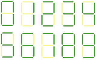
The 7-segment display is a simple collection of LEDs structured to display 0-9 based on the inputs to the device. Some can display letters or higher resolution numbers using 9, 14, or 16 segments. This post will focus on the 7-segment display because it is the most widely recognized and is the basis for my scoreboard design project.


Figure 1. Diagram (left) and functionality (right) of 7-segment displays

There are two types of 7-segment displays: common anode and common cathode. These two types refer to the way that the LEDs are connected within the device. I have not covered LEDs yet in these blog posts but all that you really need to know is that typical LEDs have an anode (+) and cathode (-). To turn on the LED, a voltage is applied to the anode and the cathode is grounded.

In a common anode display, all of the anodes (positive terminals) of the 7 segments are connected together and the cathodes are left open. The opposite is true in common cathode displays. In my limited experience, I feel the common cathode displays are preferred among designers because several of the popular ICs are designed to drive these types of displays directly whereas common anode displays tend to need additional components or specialty chips that can act as current sinks. 

Figure 2. Common Anode (left) and Common Cathode (right) connections in a 7-segment display

When universities assign labs based on the 7-segment display, the IC most often used to drive it is the 4511 BCD-to-7-segment decoder from the 4000 CMOS series. For those unfamiliar, the 4000 CMOS series is famous among hobbyists and fans of electronics from the late 1960s into the 70’s and 80’s. The 4000 series is basically a collection of discrete IC chips that perform specific digital logic functions. Logic gates, ripple counters, and decoders can all be found in the low-power 4000 series CMOS chips. Today, most of their functionality is built into microcontrollers or other ICs that can be configured through firmware to perform the same functions in a smaller package. Regardless, the 4000 series has secured its place in history and will likely live on forever in the hobbyist market.

So what does the 4511 do for 7-segment displays? Well it essentially does exactly as its name suggests…decode binary-coded decimal (BCD) to a 7-segment output. The 4511 takes in a 4-bit BCD number and, through a series of internal logic gates, generates 7 outputs that correspond to the 7 segments on the display. Below is an abridged version of the datasheet truth table for the CD4511BE from Texas Instruments. 

 Figure 3. Datasheet truth table for CD4511BE 7-segment driver IC from Texas Instruments

As the table shows, there are four binary inputs (D,C,B,A) and seven outputs (a,b,c,d,e,f,g), which correspond to segments on the display such that the correct segment lights with the right combination of inputs. For example, if you wanted a 3 on the display you would need to input 0011 (3 in a binary) into the chip. The IC would decode the input and produce the appropriate output to create a 3 on the display (in this case its 1111001). Figure 4 shows the pin diagram for the CD4511BE. 
 Figure 4. Datasheet pin diagram of CD4511BE 7-segment driver from Texas Instruments

When the chip outputs a ‘1’ it is creating a 5V potential on its output pin, which is enough voltage to turn on the LED in the associated segment. The chip is also sourcing the current to create the actual illumination.

The question then becomes how to create the inputs to the chip. In most examples switches are used to generate the 0 and 1 states. For my scoreboard project, I intend to control the inputs to the 7-segment decoder using a microcontroller, which essentially creates the interface between human inputs and IC operation.  Look for more on 7-segment displays in the future. I have built up a demo circuit and will walk through how to set one of these up in my next post.


P.S.

As a bonus, this is a BCD to 7-segment decoder I designed in my sophomore year of college. I think it may help illustrate the system level view of the 7-segment display and driver IC. It was made entirely out of discrete NAND gates and inverters rather than an integrated circuit. The picture makes it tough to see, but the bus lines on the left are tied to switches at the top, which create the binary inputs to the logic gates. Once you get the hang of digital logic, these simple circuits are actually pretty fun to put together. 


May 15, 2011

PlayStation Network Hack Timeline

The header says this is also a place for electronics news and I haven't really discussed any news stories since the impending release of the iPad 2. For anyone who isn't already aware, the PlayStation Network has begun to come back online all across the world so I put together a little timeline to show the back story.


My Thoughts:
As a PS3 owner myself, I was directly impacted when this news story broke. Since then, I have had to reset the password I use to login to various subscription services, cancel my credit card, and had my Facebook page hacked (I am not saying the two are related but the timing is hard to ignore). Still, through this whole ordeal the only thing that really bothered me was how long Sony waited to tell people that there was an intrusion on the network. Even if they felt that credit card information was not at stake, they knew early on that data from their servers had been copied or, in some cases, removed and that is enough justification to let people know so they can protect themselves. As far as I know no one has yet come forward with cases of credit card fraud related to the PSN hack, which can probably be attributed to the encryption Sony added to credit card information. 

A month has now passed since Sony's network was first compromised, but that duration doesn't bother me as much as it probably bothers some other people. You have to consider Sony's perspective on this entire issue. Right now, they are in damage control mode. If they put the network back online too soon, they leave themselves open to getting hacked immediately afterward, which would cost the company and all companies that profit from the PSN billions of dollars in total revenue. I have faith that Sony is doing all they can to patch the holes and prevent anything like this from happening again. Frankly, I think they have to be ready for future attempts because this issue is so widespread now that hackers everywhere can't wait to take a crack at breaking through the new security. 

I have my doubts about trusting Sony with personal information again but they aren't strong enough to put me off the network completely. A few months of steady operation of all PSN services will ease any tension. Until then, I'll just have to put off getting the Portal 2 DLC until I feel confident that the PSN is still alive.

May 14, 2011

EE Fundamentals: Ohm's Law

After a few conversations with more than 50% of my viewership, I have decided that maybe I got ahead of myself with some of these electronics topics. To bring things down a bit I am going to start introducing very simple, short discussions about the fundamental tools for looking at electronics. These EE Fundamentals segments will discuss the building blocks any hobbyist will need when getting into electronics. One of my goals in starting this blog was to open up the world of hobby electronics to anyone who may have a passing interest, but over these last few months I have, admittedly, gotten away from that idea. I will still be addressing more advanced topics and my personal projects in between these building block segments. 

The logical place to start this off is with the law that everyone has probably heard of and most likely forgotten in the years since high school physics: Ohm’s Law. Back in the early 1800’s, Georg Ohm published his observations regarding the relationship of voltage and current. In his experiments he applied various voltages to different lengths of wire and measured the resulting current to determine their dependence on one another. His observations became known as “Ohm’s Law”, where the current through a conductor is directly related to the voltage applied by the equation:

V (voltage) = I (current) * R (resistance)

For a visual demonstration, Figure 1 shows a linear relationship between voltage and current across and through a 1 ohm resistor. You can see in the graph that at each voltage along the x-axis there is a current of the same magnitude. Ohm’s law holds for this device as, in this example, 3 volts = 3 amps * 1 ohm. 

 Figure 1. Voltage and Current relationship in a 1 ohm load resistor

But what is the best way to visualize this concept without just looking at a graph? To answer that you must first understand the general natural of the three terms involved: voltage, current, and resistance.

Voltage:            Think of voltage, measured in volts, as an electrical pressure or force. When you apply a voltage to a conductor (say, for instance, a copper wire) you are actually pushing charges through the wire, causing them to flow away from the source of the applied pressure. The way I think if it is by picturing a garden hose. When you push down on the nozzle, the pressure built up inside the hose causes water to flow outward.

Current:            Current, measured in amps, is the result of a voltage difference across a conductor. The key to current flow is to have one end of the conductor at a lower potential than the other end of the conductor. If, for instance, you applied 5V to the end of a wire and 5V to the opposite end of the wire, the net current flow would be zero because there is no potential difference to draw the charges. Just as heat transfer occurs when one area is warmer than another, current flow occurs when one side of a conductor is at a lower potential than another.


                          Humans often perceive current as the flow of electrons from a positive voltage to a lower voltage or “ground” at 0 volts. This is inaccurate in a few different ways. First, the word “current” is commonly associated with the flow of electrons. However, if you noticed in my description of voltage I used the term “charge” rather than electrons to describe current flow. The reason for this distinction is because the flow of current depends on the material you are working with and the voltage applied. In some cases, positive charges (called holes) make up the bulk of what is perceived as current flow. I would like to go into the details on this one but semiconductor physics may be a bit much at this point.


                          The second thing worth noting about current flow is that we analyze circuits based on the “conventional current” model, where charge flows from positive to negative. Essentially, this means we are modeling charge flow in terms of positive charges rather than electrons, but in most cases they are still referred to as electrons. It turns out this is of little consequence as long as the polarities of all voltages and currents are kept consistent when analyzing the circuits. As Figure 2 shows, we can model current flow from the positive lead of the 5 volt source to ground (at 0 volts) as long as we consider the voltage drop across the 100 ohm resistor as positive.

Figure 2. Current flow in a simple circuit

Resistance:      Electrical resistance, measured in ohms, is physical property of a material characterized by its ability to resist the flow of current. Everything everywhere has electrical resistance to some degree. Some materials have very low resistance to the passage of current (conductors) and others have a very high resistance (insulators). Again, the resistance of a specific material comes down to physics that I don’t want to touch on in these posts. However, resistance is highly dependent on a few key factors: length of the conductor, the cross-sectional area, and the temperature of operation.

Now let’s re-examine Ohm’s law with this improved understanding. Ohm’s law states that the amount of pressure you must apply to a conductor to get a desired charge flow is equal to that charge flow multiplied by how much the conductor will try and oppose it. Therefore, if a material doesn’t want to let current pass through it, you really have to push hard to get it to cooperate (resulting in high voltages). The same argument applies for passing large amounts of current through a material with very little resistance. Figures 3 and 4 show how to create the same current flow under two different voltage/resistance combinations. In Figure 3, a 5 volt source and a 100 ohm resistor produce a current of 50 milliamps. In Figure 4, the voltage has increased by a factor of 10. To get the same current as Figure 3, the resistance must increase by the same factor according to Ohm’s law.

Figure 3. 50 milliamps of current generated with a 5V DC source

 Figure 4. 50 milliamps of current generated with a 50V DC source

We call components that adhere to Ohm’s law “ohmic” and those that do not “non-ohmic” (clever I know). Resistors are ohmic because an increase in voltage across the resistor creates a linear escalation in the current flowing through it. Examples of non-ohmic components include capacitors, inductors, sausages (unconfirmed), and diodes.

So that is Ohm’s Law in a nutshell….at least using DC power. AC (alternating-current) Ohm’s law is basically the same idea but slightly more complex (pun intended for anyone who gets it). This went a little longer than I was shooting for but having a solid understanding of the fundamentals makes more complex ideas easier to digest.

May 5, 2011

Scoreboard Project: Exterior Design

I once made a joke that I should build a scoreboard to keep score of the pick-up basketball games that a few of my friends play since I would be more useful there than on the court. Eventually I began to feel that building a scoreboard could be a really interesting project because it would require more sophisticated designs than I had previously attempted.

That was all about 4 months ago and I have been thinking about this project off and on ever since. Today, I decided to post my vision for the exterior design that I put together in Google SketchUp. There is nothing really unique about the look of it – pretty much the same as any scoreboard anywhere. 


 Figure 1. 3D Picture of the Scoreboard Design

Figure 2. Front View of the Scoreboard


The one thing I did want to highlight is the use of LEDs. I am going to model the control scheme for this board based on the 7-segment display, which is basically a smaller version of the orange and blue numbers you can see in the picture. The drivers for these 7-segment displays typically use logic gates to decode binary inputs and drive the individual segments off and on. I will explain this more in a future post but for now I just wanted to put something out to compare to my final board design (assuming I ever actually implement this project). 

I will periodically post updates showing my progress, or lack thereof, building this scoreboard and discuss other topics in between. If I worked on this design constantly I would probably lose interest or do a poor job because I just wanted to get it done. I have found that when I work on several things at once and do little pieces at a time I ultimately see more through to the end. My goal is to highlight some of the considerations/problems that are important to the design process and hopefully learn some new stuff along the way.

Let me know what you think of the layout. Comments are always welcome!


May 2, 2011

Weekend Mod

This post is dedicated to a quick mod I did to a piece of equipment I had lying around on my bench. Anyone with some level of dedication to home electronics will probably recognize the “helping hands” and magnifier combo in this picture.

Mine was too cumbersome to use as an all-in-one tool but I did like the alligator clips mounted on the posts because they were useful for tricky soldering jobs. I decided to modify the magnifier piece to include more LEDs with a better driver circuit and mount the magnifier onto an old Luxo lamp from the 70’s I had in a junk box. This post will largely be a photo montage of my progress.


This is the crappy circuit that was originally in the magnifier. It’s mostly made up of flimsy wire and cheap LEDs.


I took the LEDs from an old string that was meant to be mounted underneath a bed. There was some internal drive circuitry that I also ripped out to use in place of batteries.


The pictures to the left show the battery cover on the magnifier. I drilled a hole in the cover and mounted the DC input jack on top so that the driver circuitry would be hidden once the final product was assembled.


Originally, the magnifier casing was silver like the battery cover. I painted the rest black to get a cool two-color scheme going. I also drilled about 6 additional holes around the bottom side to mount some more LEDs.


This is a picture of all the new LEDS wired up and held in place with a little bit of hot glue. The red and black wires are power and ground respectively and feed back to the drive circuitry mounted under the battery cover. I also added the magnifier lens back in.


These are a few pictures of the assembled unit with the new lights. The black wire coming out of the top of the battery compartment is the power supply equipped with a SPST switch so I can easily switch the LEDs off or on without having to unplug anything.


 The final (sort of) product! I took the metal frame from an old lamp and painted it black to match the scheme on the magnifier. In the future, I am going to create a swivel base so that I can rotate the magnifier when I need to use it. As of right now the lens piece rotates on a sphere so I can position it to any angle and lock it in place with a wing nut and screw I have holding the lens to the metal frame. I wanted to post this because I made it completely from stuff I had lying around my house in only a few hours. As much as I enoy building a circuit from scratch, I am continuously amazed by the hacker/maker community and the incredible projects they create out of other people’s garbage. It may not be up to the quality level of a store bought magnifier, but it cost me $0 as opposed to $100+ for retail.