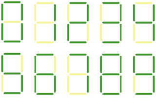
As a complement to my post about my scoreboard project, I thought I would discuss the basics of the 7-segment display. Anyone reading this has probably seen one in their lifetime without even realizing it (or caring). Today, 7-segment displays are slowly being overtaken by software GUIs on LCD/LED screens but they are still very widespread. Next time you are in an elevator, take a look at the way the numbers are displayed as you move through the floors. You can appreciate the glory of the 7-segment display while avoiding eye contact with anyone else who happens to be in there with you.
The 7-segment display is a simple collection of LEDs structured to display 0-9 based on the inputs to the device. Some can display letters or higher resolution numbers using 9, 14, or 16 segments. This post will focus on the 7-segment display because it is the most widely recognized and is the basis for my scoreboard design project.
Figure 1. Diagram (left) and functionality (right) of 7-segment displays
There are two types of 7-segment displays: common anode and common cathode. These two types refer to the way that the LEDs are connected within the device. I have not covered LEDs yet in these blog posts but all that you really need to know is that typical LEDs have an anode (+) and cathode (-). To turn on the LED, a voltage is applied to the anode and the cathode is grounded.
In a common anode display, all of the anodes (positive terminals) of the 7 segments are connected together and the cathodes are left open. The opposite is true in common cathode displays. In my limited experience, I feel the common cathode displays are preferred among designers because several of the popular ICs are designed to drive these types of displays directly whereas common anode displays tend to need additional components or specialty chips that can act as current sinks.
Figure 2. Common Anode (left) and Common Cathode (right) connections in a 7-segment display
When universities assign labs based on the 7-segment display, the IC most often used to drive it is the 4511 BCD-to-7-segment decoder from the 4000 CMOS series. For those unfamiliar, the 4000 CMOS series is famous among hobbyists and fans of electronics from the late 1960s into the 70’s and 80’s. The 4000 series is basically a collection of discrete IC chips that perform specific digital logic functions. Logic gates, ripple counters, and decoders can all be found in the low-power 4000 series CMOS chips. Today, most of their functionality is built into microcontrollers or other ICs that can be configured through firmware to perform the same functions in a smaller package. Regardless, the 4000 series has secured its place in history and will likely live on forever in the hobbyist market.
So what does the 4511 do for 7-segment displays? Well it essentially does exactly as its name suggests…decode binary-coded decimal (BCD) to a 7-segment output. The 4511 takes in a 4-bit BCD number and, through a series of internal logic gates, generates 7 outputs that correspond to the 7 segments on the display. Below is an abridged version of the datasheet truth table for the CD4511BE from Texas Instruments.
Figure 3. Datasheet truth table for CD4511BE 7-segment driver IC from Texas Instruments
As the table shows, there are four binary inputs (D,C,B,A) and seven outputs (a,b,c,d,e,f,g), which correspond to segments on the display such that the correct segment lights with the right combination of inputs. For example, if you wanted a 3 on the display you would need to input 0011 (3 in a binary) into the chip. The IC would decode the input and produce the appropriate output to create a 3 on the display (in this case its 1111001). Figure 4 shows the pin diagram for the CD4511BE.
Figure 4. Datasheet pin diagram of CD4511BE 7-segment driver from Texas Instruments
When the chip outputs a ‘1’ it is creating a 5V potential on its output pin, which is enough voltage to turn on the LED in the associated segment. The chip is also sourcing the current to create the actual illumination.
The question then becomes how to create the inputs to the chip. In most examples switches are used to generate the 0 and 1 states. For my scoreboard project, I intend to control the inputs to the 7-segment decoder using a microcontroller, which essentially creates the interface between human inputs and IC operation. Look for more on 7-segment displays in the future. I have built up a demo circuit and will walk through how to set one of these up in my next post.
P.S.
As a bonus, this is a BCD to 7-segment decoder I designed in my sophomore year of college. I think it may help illustrate the system level view of the 7-segment display and driver IC. It was made entirely out of discrete NAND gates and inverters rather than an integrated circuit. The picture makes it tough to see, but the bus lines on the left are tied to switches at the top, which create the binary inputs to the logic gates. Once you get the hang of digital logic, these simple circuits are actually pretty fun to put together.


1 comments:
Hi, I really like your circuit, I've actually put it down but the seven segment doesn't display the numbers, rather it displays only 3. What display did you use
Post a Comment