It seems so long ago that I actually posted about electronics on this supposed “electronics blog”. I have been sort of busy lately with family and work so I haven’t really made much progress on any projects worth noting. Instead, I figured I would write the second part to the EE fundamentals piece I put up just over two months ago. The first segment looked at finding the equivalent resistance of series and parallel connections. In this entry, I will discuss how voltage and current flow through these two types of connections. Let’s get to it.
In my opinion, when you look at a circuit and attempt to figure out what is going on you need to first identify the types of connections so you can track the distribution of voltages and currents throughout the circuit. That being said, how do we know what the voltages and currents should be? It turns out this is easy to do using ohms law and knowledge of resistances connected in series and parallel – hence why I covered those first.
Series Connection
In series connections, the same current flows through each component connected in series. So if you have two resistors connected in series and you apply a voltage you would see the same current passing through each resistor when examined individually. Figure 1 shows that 4 milliamps of current appears at each point along the circuit path. What that means is that the current flowing into one side of resistor R1 is the same magnitude as the current flowing out of R1, into R2, and out of R2.

Figure 1. Current flow in a sample series circuit
Though each resistor has the same current passing through it, the voltage drops across them are different. According to Ohm’s Law, voltage is equal to current multiplied by resistance, and each resistor has a different resistance. When you do the math it turns out that the voltage drops across each of the resistors add up to the source voltage, another important aspect of circuit analysis (more on this in another EE fundamentals entry). Figure 2 shows, under the same conditions as Figure 1, the voltage drops across both series resistors in the circuit.

Figure 2. Voltage drops in a sample series circuit
Parallel Connection
Unlike series circuits, parallel circuits do not have the same current through each resistor (unless the resistors are equal in magnitude). Instead, the current through each resistor is regulated by the voltage across each “branch”. Where current is constant through a series circuit, voltage is constant across all branches of a parallel circuit. In this case the constant voltage is equal to the source voltage (100V) meaning that the current through each resistor is going to be equal to 100V divided by the total resistance in the branch. If you were to add all these currents up, you would find that the sum is equal to the current provided by the voltage source (i.e. battery, external power supply, USB port). Figure 3 shows how this is the case.

Figure 3. Current and Voltage breakdown of parallel circuit
R1 and R2 are in series so the total resistance of the first branch (reading from left to right) is 25k. In each subsequent branch there is only one resistor present therefore the resistance in each branch is equal to the nominal value of the resistor. This results in a different magnitude of current flowing through each branch.
Now, for anyone paying attention to my last post about series and parallel circuits you might think – hey, can we reduce this circuit down using parallel resistance equivalents and find the total current supplied by the source? If there were such a person reading this that actually thought that then I would say obviously yes you can, but, since I know no such person exists, let’s go through the steps.
First we should look into the circuit from the source’s perspective. Looking into the circuit from the left (from the voltage source) we see a 25k (effective) resistor in parallel with a 10k resistor and a 5k resistor. Using the steps from my last post we find that the equivalent resistance is equal to approximately 2941.2 ohms. The equivalent model looks like Figure 4 below.

Figure 4. Equivalent circuit of Figure 3
There are two important things to note about this equivalent model. First, the equivalent resistance is lower than any branch resistance in the original parallel circuit as it will ALWAYS be when you find the equivalent resistance of two parallel branches. Second, the voltage is 100V across the equivalent resistance in the circuit, but it is also 100V across each branch of the original circuit.
Series-Parallel Connection
In case you were wondering about series-parallel connections, the same rules apply you just need to identify what types of connections you are seeing. If, for example, you added a 1k resistance in between the source voltage and the three parallel branches from Figure 3, you could still figure out the current drawn from the battery by reducing the 3 branches to their equivalent resistance. However, you would need to add an additional 1k-ohm to the total circuit resistance seen by the source when calculating the total current draw. I have put the example circuit and the measurements in Figure 5. The voltages have been approximated for simplicity. The actual results are around 25.4 and 74.6 volts on the appropriate nodes.

Figure 5. Series-parallel circuit analysis
That’s just about everything I have to say about voltages and currents in series and parallel circuits. I encourage you to look for other sources on the web and practice figuring out how to analyze these types of circuits if you are interested. While I try to explain things as best I can on this site, it’s hard to look at a subject you have studied for some time and try to act as if you are seeing it for the first time. As always, I hope someone will take something positive away from these entries.
Pop Quiz
I like giving these quizzes after the EE fundamentals segments so I think I will make it a regular thing.
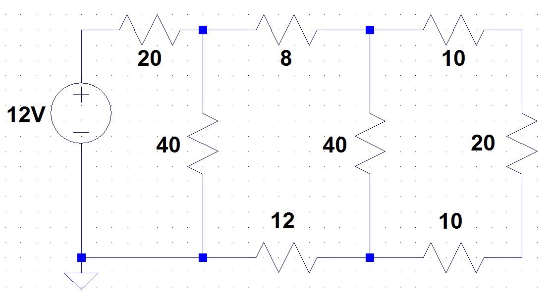
Question: Find the total power dissipation in this circuit.
HINT: Power = current * voltage in the circuit element of interest. By summing the power of all the dissipative elements in the circuit, you can find the total dissipation. Assume the wires connecting the resistors are idea conductors - i.e. they do not dissipate power or drop voltage. Good luck.
1 comments:
Is it 3.6 watts? Do you actually have to look at each branch? I just reduced the circuit to a resistor of 40 ohms.
Post a Comment