In my last post I talked about the 7-segment display and its popularity among digital displays. For the first time in this blog, I figured I would build up a sample circuit just as a small demo to prove what I am talking about actually works in practice.
Figure 1. My demo 7-segment circuit layout
In the picture above, I have wired up a simple 7-segment display using the CD4511BE driver IC from Texas Instruments (see my last post for some data sheet diagrams about the chip’s operation). The breakdown of the functional blocks goes like this:
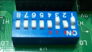
Pink – These are the input switches that allow for any binary number from 0-9 to be entered into the 7-segment driver IC. The resistors closest to the switches are known as pull down resistors because they make sure the voltage seen by the IC is either 0V or 5V (0 or 1). You can enter the binary number using the switches as shown in Figure 2. From left to right, the number translated to 5 in decimal (0101 in binary).
Figure 2. Input switch terminal used to control the display
Blue – The CD4511BE chip from Texas Instruments. This chip is the brains of the system. It interprets the inputs from the switches and sets the appropriate outputs high according to its internal logic (see the truth table from my last post).
Yellow – Current limiting resistors are used on each of the seven outputs from the IC to protect the chip from trying to source to much current and keeping the led from running away and burning out. In this case, I used 470 ohm resistors to limit the current based on a 2V turn on voltage of the LEDs in the 7-segment and 5V coming from the IC on each output lead.
Red – A 7-segment display using red LEDs. There are several different colors available, but each will require certain voltages and current limiting resistors. If you are ever trying to figure out which resistor to use, I suggest looking up a current limiting resistor calculator online if you don’t want to deal with equations.
There really isn’t too much more to say in this post. Just as an example, Figure 3 shows the output of the 7-segment display using the input from Figure 2.
Figure 3. The 7-segment display as a result of the inputs from Figure 2
My goal with this small segment was to introduce a relatively simple electronic system because, as I have said, I am basing my scoreboard design on this layout.
As a side note, if you start bread boarding circuits, I highly suggest color coding your wires so you know what is what. In Figure 1, I used the power and ground convention of red and black respectively (*NOTE: DO NOT ASSUME THIS IN HOUSE WIRING!! Black is often the hot wire and you could get yourself killed if you don’t know what you are doing). I used yellow wires for the inputs from the switches and green as the outputs to the 7-segment display. In some cases, I attached a resistor directly to the output of the IC so a green wire was not necessary. This all may seem like a diversion from the main topic, but I have found these small tips very useful in circuit design.


0 comments:
Post a Comment